The term “reality capture” refers to technologies used to capture the physical world and transforming it into digital data. It’s typically used to document existing conditions, create accurate 3D models, perform clash detection, or analyze spatial relationships.
Reality capture technologies were first used in civil and architectural engineering because of its limited level of accuracy aligned with these disciplines. But now, the precision of modern laser scanning enables manufactures to embrace this technology and incorporate it into their design and manufacturing workflows.
Following are 10 examples of how reality capture can be used in manufacturing.
CAD design vs. production
The worlds of CAD design and production are drastically different. CAD tools can produce highly accurate, perfectly precise 2D drawings and 3D models. The reality of production is quite different. The real-world versions of our design will never perfectly line up with our original CAD designs. This is where the practice of dimensional tolerancing is so important.
Modern manufacturing can now incorporate reality capture laser scanning to accurately record a real-world component and bring it back into the digital arena where it can be compared to the original CAD design.
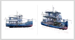
The image below shows the original hand drawings of an old ship design overlaid on a scanned section of a rusted hulk currently being restored. This workflow allows manufacturers to check and monitor design tolerances and confirm that the real-world production accurately depicts their original CAD design.
Greenfield and brownfield site acquisition and evaluation
One of the most traditional uses of reality capture relates to greenfield and brownfield site acquisition and evaluation. Manufacturers often use reality capture scanning to evaluate and acquire precise measurements and 3D representations of new or existing spaces for interfacing or installing equipment. The ability to visualize and interact with a digitally accurate version of the space you are working in allows designers to avoid costly collisions and interferences between the new equipment being installed and the existing structure of the space.
The Autodesk Factory Utilities software provides a good example of this workflow. The Factory Utilities allow you to place a 2D drawing on a floor plane to place your factory assets. But in reality, the space you are working may have many potential interferences from overhead infrastructure. Adding a reality capture scan of the building space to the 2D floorplan allows you to place your assets without costly interferences or collisions with the existing structure. See image below.
Reverse engineering
Manufacturers must often deal with legacy components that were designed and produced long before the digital era. In many cases, the original design specifications of these components have been lost. If one of these components ever needs to be replaced, where would you start?
Reality capture allows manufactures to digitize these components with laser scans and place them in their CAD design software. The surfaces and outlines of the part are then extracted and recreated producing the 3D models and 2D design documents that can be used to produce replacement parts. Modern scanners are much smaller and can often scan machine parts in place, as with the bearing block shown in the following image.
Orthographic image development
There are times that a full 3D model is not required. In some cases, simple 2D drawings can be developed by directly tracing the 3D scan. Floorplans or layout plans are good examples of this. These workflows are enhanced by the ability to display the reality capture scan in orthographic mode. This visualization removes all depth of field and displays the scan as it would be drawn in traditional orthographic projection.
The following image shows the same hoist gear and bearing in perspective and orthographic mode. The orthographic version can be used to develop the desired replacement gear.
Hybrid layout design
Reality capture scans can be useful in representing equipment in a facility layout project. These scans can be cropped to show just the desired machine. The scan can then be included in the CAD layout of the facility, bypassing the need for traditional 3D modeling. Including simple top-down surfaces or sketch representations in the scan allows the creation of 2D layout drawings that include both the 3D models and the reality capture scans.
The following image shows a sample layout containing both traditional 3D models and reality capture scans. The image also includes the resulting drawing document of the combined layout.
Hyper-accurate measurements
One of the earliest examples of reality capture used in manufacturing is with probe arms for hyper-accurate measurements. These arms extract coordinates from a variety of surfaces and objects and allow the numeric values to be analyzed and displayed in various CAD systems. Autodesk Inventor can import these individual points into a 2D or 3D sketch allowing the designers to create geometry or surfaces based on real world coordinates.
Including anatomical forms in mechanical design
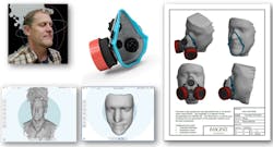
Modern 3D CAD applications can generate most any kind of traditional mechanical shape necessary for a design. But they often fall short when trying to include a natural or anatomical shape like a human body or face. Reality capture allows these complex forms to be scanned and imported into your CAD application where they can be used to generate surfaces that interact with your mechanical design. It is quite common to see custom products manufactured specifically for a single individual based on the person’s scanned form.
Modeling in context of a scan
When we begin any new 3D design project, we often have some existing drawings or documents that provide a starting point. However, in many cases, manufacturers have to deal with existing designs that pre-date modern CAD applications and have no proper drawing documentation. In these situations, reality capture is a great way to digitally record the existing state of the design and provides an essential starting point where the modern 3D design can begin.
Designers can create the new 3D model inside the scanned point cloud of the original design. Modeling in context of a scan allows manufactures to systematically reconstruct a new 3D model based upon the reality capture scan of the original.
The following image shows a water plant recreated in Autodesk Inventor based on a point cloud of the original layout. In many cases, modern equipment and piping parts were substituted for out-of-date components.
Spatial analysis
When you are adding or appending an existing design with new components, you need to ensure there is enough room to install the new parts so that they don't interfere with the existing layout. Modern spatial analysis often requires the new and old components be 3D modeled using interference analysis. With reality capture and spatial analysis tools like Autodesk Navisworks, manufacturers no longer have to create 3D models of existing designs. With this technology, they can perform a clearance analysis between the new 3D design and a point cloud scan of the original layout.
The following image shows a clearance analysis between a new pipe run and an existing boiler layout.
Transferring formats
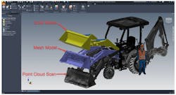
Modern manufacturing deals with reality capture in various formats. As such, it is often necessary to translate a reality capture scan from one format to another based upon the 3D modeling or manufacturing requirements. It is also important to note that many manufacturers need a 3D solid model as their final deliverable. The Autodesk Product Design Suite offers several ways to deal with point scans and mesh scans. For example, Autodesk ReCAP provides the ability to translate point scans to mesh if required. Autodesk Fusion allows you to convert a watertight mesh into a solid body under the appropriate conditions. Autodesk Inventor supports all three scan states, allowing hybrid designs of point, mesh and solid in the modeling environment.
Rusty Belcher is a manufacturing solutions consultant, providing implementation, training and support services for Autodesk manufacturing products.


