It’s been widely reported for years now that industry is the biggest global user of energy and that the motors used in industry are responsible for much of that energy use. According to a report from ABB, industry accounts for 42 percent of the global energy use, with electric motors using 2/3 of that energy.
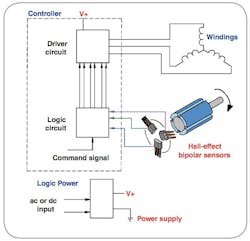
To help address this issue, a great deal of attention has been focused on one of the more common motors used in industry—the brushless DC (BLDC) motor. A well-recognized method of improving the efficiency of BLDC motors is the incorporation of Hall-effect sensors.
Selecting the correct bipolar latching Hall-effect sensor integrated circuit for electronic commutation in BLDC motors plays a big role in the efficiency of these motors and can, therefore, significantly affect the reliability and performance of many applications, including robotics, portable medical equipment and HVAC fans.
Honeywell Sensing and Control has released a white paper—How To Select Hall Effect Sensors for Brushless DC Motors—to help motor designers and users better understand the impact of Hall-effect sensors on BLDC motors.
Because BLDC motors use electronic instead of mechanical commutation to control the power distribution to the motor, the white paper points out that latching Hall-effect sensors, mounted in the motor, are used to measure the motor’s position, which is communicated to the electronic controller to spin the motor at the right time and in the right orientation.
Principal design characteristics to consider in a bipolar latching Hall-effect sensor used to commutate a BLDC motor include sensitivity, repeatability, stability-over-temperature, and response time.
Since a magnetic field is required to activate a Hall-effect sensor, “sensitivity level is based on the placement of the sensor to the magnet, the air gap, and magnet strength. Product datasheets should indicate the magnetic field strength (measured in Gauss), required to make a bipolar Hall-effect sensor change state (operate and release),” notes the Honeywell white paper. “A high sensitivity sensor, typically rated at less than 60 Gauss, allows for the use of smaller magnets or less expensive magnetic materials, which is increasingly important as the prices for rare earth magnets continues to increase. High sensitivity also allows for a wider air gap, which means the sensor can be placed further away from the magnet and still be very reliable, while providing some design flexibility.”
Repeatability refers to the Hall-effect sensor’s latching time. “It goes hand-in-hand with high sensitivity, as it allows the sensor to be more repeatable,” the paper states. “When the sensor output turns on, it directs current through the coil windings in the stationary part of the motor. This current produces a magnetic field that interacts with the field from the permanent magnets on the shaft and causes the shaft to spin. As the magnet rotates past the sensor, a highly repeatable sensor changes state at the same angular position each time the magnet passes by. A highly repeatable sensor is one that has a consistent response time, which will maintain all of the angular measurements very close to the same value.”
Similar to repeatability, stability, according to the Honeywell white paper, refers to how much the angular position changes versus temperature or voltage. For example, if the sensor output changes state at five degrees at 25 °C, where does it change state at 125 °C? The Gauss level required to turn a part on at 125 °C needs to be as close as possible to the Gauss level required to turn a part on at 25 °C. So, if a part operates at 30 Gauss at 25 °C, does it operate around 30 Gauss at 125 °C, or does the operate point shift to, for example, 50 Gauss or 5 Gauss? This is important because stability-over-temperature, coupled with high sensitivity, is needed for precise position detection. Magnetic stability also helps improve jitter performance for BLDC efficiency, and results in less speed variation.
Response time is the time it takes for the output of the sensor to change state. For example, if a sensor has an operating point of 30 Gauss, and a 30 Gauss magnetic field level is applied to the sensor, the response time is measured from the point when the 30 Gauss field is applied to when the output changes state. A faster response time to a change in the magnetic field delivers greater efficiency in commutating a BLDC. If a sensor switches at a different magnetic field level than what is required due to slow response or delay, this could result in accuracy errors.
View the complete How To Select Hall Effect Sensors for Brushless DC Motors white paper from Honeywell.

