Q: How are drag chain and torsion-rated cables designed and manufactured differently from each other?
A: In many ways, with respect to the environment each cable will be installed in, they are very similar. Before those details are discussed, let’s talk about the most basic material found in the majority of industrial cables, the copper strand. The key thing to remember is that all copper strands, no matter how they are drawn, how many are used per conductor, or how they are stranded together, have memory. For example, think of a wire coat hanger. If you bend it in a particular direction and then attempt to bend it back to the original position it will not be exactly as it was before. The same applies to copper strands in a multi-conductor industrial cable. This is fine for a stationary or fixed applications, but it creates the most basic of challenges for a cable manufacturer when that cable will be bending millions of times in a 2D (drag chain) or 3D (robotic) application. When designing and manufacturing these 2D- and 3D-style cables, managing the memory of each strand and conductor plays a major role in design efforts. The more demanding the mechanical application, the greater the cable’s performance characteristics must be. That means progressing from simple bunch or unilay construction for stationary cable to concentric with a short lay length (2D) or concentric with a longer lay length (3D). As the performance needs increase, cables also switch from PVC to PP insulation, and to PUR or TPE jacket compounds.
Q: What are some of the cable design considerations for torsion/robotic-rated cables?
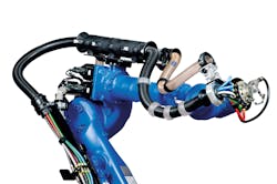
A: Torsional (3D robotic) cables are required to endure many of the same environmental factors as drag chain cables. As previously mentioned, understanding the entire scope of the application is needed in order to make the proper recommendation or design the best solution. Although the flexing of the cable along its entire length is not present in a torsional application as it is with a drag chain application, there is the added rotational stress applied to the cable. This is demonstrated on an articulated robot when axis four rotates in one direction and axis six rotates in the opposite direction. A cable manufacturer must now consider the memory of the copper strands as it relates to that additional stress. With this in mind, we should understand that the torsional value (+/- XXX°) is one of the most critical parameters of a torsional cable. When comparing cables from various suppliers, use this as the base line for comparison. A cable that is +/- 180° per meter may be acceptable for a four-axis palletizing robot, but it may not be best suited for a welding robot in an automotive plant. Also, stating a cable is designed to “withstand torsional applications” is simply not enough to determine if it is the proper solution for the application.
Q: How does acceleration, travel speed, and torsion requirements all impact the material selection and/or development of new compounds for cables?
A: Cables in highly dynamic applications must withstand acceleration forces up to 50 m/s² and rapid, unforgiving decelerations (the whiplash effect). It seems counter-intuitive but utilizing materials with a certain amount of stiffness is crucial to longevity. If you compare standard tray cable with class 6 stranding to a drag chain-rated cable of the same construction, you should notice the “high performance” cable will seem to have more of a rigid feel even though they both utilize pressure extruded jackets. Choosing the wrong material could increase overall weight per foot and shorten the lifespan of both the cable and the cable management system (drag chain/dress pack).
Q: What is the number one design flaw you see in the field with drag chain applications?
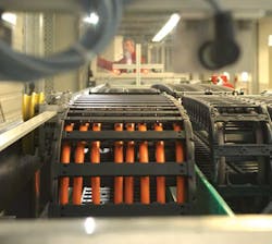
A: Many engineers are somewhat designed into a corner. The drag chain is not a high priority component in the design process. But at some point, the cables and hoses need to get from the panel to the X axis over to the Y axis and then on to the Z axis, in the case of a gantry robot. What design engineers are left with may be a physical envelope that does not allow for the proper geometries needed to manage the fill package correctly. Machine repairs and upgrades can be a source of this issue as well. There have been instances where an electrical contractor has fished a PVC-jacketed Ethernet cable through the drag chain on top of a TPE-jacketed servo cable, while completely ignoring the safety factor needed for free movement because “there was room.” Whether the fill package was originally designed with too much content or it happens over numerous machine repairs or upgrades, a drag chain stuffed full to the brim will have a decreased lifespan and much more downtime.
Q: What other systemic design flaws do you encounter in the field?
A: There are several but I’ll only go over a few I see the most in my travels. Uneven weight distribution is the most often design flaw next to an overfill situation. Over time this may lead to the drag chain leaning to one side. This will cause undue stress on the individual links of the drag chain, thus reducing the lifespan of the drag chain itself, especially in a long travel, gliding application. Next on my list is the lack of internal separation. This can cause a myriad of issues. The rule of thumb for separation is to create a cavity with 10% safety factor for cables and 20% safety factor for hoses. This means if a cable has an O.D. of 20 mm, the inside dimensions of the cavity it travels in should be 22 mm x 22 mm. Adding internal dividers and separators does increase the initial cost of a drag chain, but over the lifespan it will reduce total cost of ownership and downtime. Another systemic design flaw that causes a good share of downtime and failure is the physical placement of each component. Going back to the example in the previous question, PVC and TPE jackets have different levels of abrasion resistance (a.k.a. friction coefficients). Placing dissimilar jacket types next to each other without the proper separation as mentioned before, can cause the cables to possibly bind and wear prematurely. Finally, the last design flaw is one that is a pet peeve of mine. It’s typically found in older drag chains in an MRO situation… zip ties… everywhere. The only “strain relief” needed is at each end of the drag chain.
Q: What are some of the best key practices when designing and building a plug-and-play drag chain solution?
A: I would recommend this above all else; determine what your fill package will consist of first. Even if you are not sure about some of the other parameters the fill package will drive the mechanical envelope the drag chain must operate in. Matching all components properly to the application is another key. An example would be using cables that are rated for an acceleration of 5 m/s² when the real-world acceleration is 20 m/s². Will the cable work? Possibly, but for how long? Confirm the bend radius of the drag chain will accommodate each cable/hose bend radius. Cables that are constantly stressed longitudinally beyond their specified bend radius will fail prematurely. The last one I will mention relates to the use of support and guidance systems, sometimes referred to as guide troughs. These are sort of like a seat belt for your drag chain. They keep the drag chain properly aligned (no snaking), ensuring there is proper support and a uniform, obstruction free path in which to operate.
Q: What are some of the best indicators that an end user can look for to determine if their drag chain is beginning to fail?
A: A clear indicator that you may have an issue is when frame stays are missing or appear to be partially unsnapped from its link. This indicator is tricky because it could be a symptom of a deeper, unseen systemic issue. Maybe you have a drag chain that looks “twitchy” as it moves from the retracted to the extended position. I see this issue quite often. The possible causes could be one or more links are beginning to fail or there is debris in the drag chain and/or guidance system. Look for cables that begin to crossover their neighbors or show signs of cork screwing. This is one sign that should be looked at sooner than later, similar to the low tire indicator on your car. These issues should be evaluated by an experienced field support representative to determine your best course of action for repair, redesign, or replacement.


