Advance Your PLC Configuration Method - Saving Time, Trimming Costs
FDT Device Type Managers (DTMs) simplify the tasks of configuring control systems, providing a common format that’s easy to work with. DTMs from manufacturers or independent suppliers reduce development time and cut costs.
To configure a control system with the associated field devices for the term, a few actions must be taken. They include:
- Defining the topology
- Defining the process data transferred via the fieldbus
- Parameterizing the fieldbus-specific values such as timers
- Device-specific settings
Either discrete tools or an integrated, manufacturer-specific solution can be used. With FDT, it is possible to implement a manufacturer-independent solution.
FDT concept for the fieldbus configuration
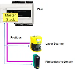
By using the Fieldbus Master DTM and Device DTM (slaves), in a PLC programming system, required functions can be made available via FDT. The standardized FDT interface allows you to use DTMs from various manufacturers in one application. With the Master DTM, fieldbus-specific parameters - TCP/IP addresses, SNMP settings and quality of service for a Modbus TCP network - are set. For PROFIBUS and others, the baud rate and timer settings are set (figure 3).
The DTM provided by the device manufacturer is used for the slave. In this case, the manufacturer can use the DTM's graphical user interface to provide a convenient device configuration. For field devices with a larger range of functions, there are many more options than with a device description like GSD. Here, the manufacturer can use intelligent functions to differentiate themselves from their competitors. Figure 4 shows a device's graphical user interface. The interface is tailored to the device's functions, showing how the variables/states determined by the devices' I/O can be arranged. Other functions can be called up from the left-hand toolbar in the DTM.
Generic DTM
Some device manufacturers do not provide DTMs for their devices, while sometimes devices require a specially designed user interface for the configuration. In these cases, you can use a generic DTM to integrate the device into an FDT system. Figure 2 shows a graphical DTM for a PROFIBUS device with a GSD. In this case, the generic DTM interprets the GSD and displays the data on its user interface. The data is usually shown as a table and can be edited by the user (figure 5). Various FDT service providers offer such generic DTMs. Some manufacturers integrate FDT tool vendors integrate them into their systems.
Process data
DTM devices can also be used to configure process data. This is data that the device sends or receives via the fieldbus. The PLC tool can use the ProcessData DTM interface to determine the process data description for a device. This interface describes the structure of the process data. It contains the names, the data type and the transfer direction (sending/receiving). The PLC programming system can use this information to create the appropriate programming variables.
However, the process data description is fieldbus-specific, i.e. the PLC tool must also implement this for each fieldbus.
Summary and outlook
FDT is a tried-and-tested software interface for integrating automation components into software tools. Using FDT results in open and flexible automation systems. Employing DTMs to integrate different devices into various tools makes it possible to achieve standardized device management and consistent data management. Utilizing DTMs provides significant savings by reducing development time and expense, giving developers and maintenance personnel a standardized operating environment.
Authors