Industrial Machine Vision: Why Object-Detection Alone Isn’t Enough For Robot Automation
Key Highlights
- Object detection is only the first step; translating visual data into physical robot actions requires precise spatial calibration and multi-stage processing.
- Continuous, automated calibration routines are vital to maintain accuracy in dynamic industrial environments, accounting for physical drift over time.
- Combining 2D vision with 3D depth sensors enables accurate identification of objects' position, orientation and surface topology, essential for complex tasks like bin-picking.
- Confidence scores from vision models must be managed with strict rules; uncertain detections should trigger remediation routines or system halts to prevent errors.
- Adaptive handling based on object material properties ensures delicate objects are protected, while rigid items are manipulated with appropriate force and speed.
- Vision data, when aggregated over time, provides valuable insights into process inefficiencies, defect patterns and system reliability, supporting continuous improvement.
- Designing robust vision-guided systems involves integrating perception, physical context, error management and mechanical adaptability to meet industrial safety and quality standards.
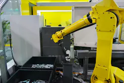
Imagine a factory floor. A digital monitor is mounted beside a robotic work cell that displays a live feed of a deep container filled with randomly oriented mechanical components. When a new bin arrives, the artificial vision software quickly executes an inference pipeline. On the screen, the target object has been identified and isolated with high statistical probability. But inside the physical work cell, the six-axis robotic arm remains motionless–the robot still lacks the information required to move. This gap in operations highlights one of the most important discrepancies in modern machine building: object detection is the preliminary output of a robot-vision system, not the final objective. To bridge this divide, engineering teams need to look into strategic decisions focused on spatial calibration, deep sensor integration, strict confidence rules and adaptive mechanical execution.
Customers want to feed components into a line with less sorting, manipulation and orientation before the machine takes over. That requirement shaped our investment in machine vision. The machine must cope with parts as they arrive, while the customer spends less time preparing each part for a rigid vision setup.
Detection produces an image result, not a robot instruction
To design a reliable automated production line, engineers must separate the abstract milestones of computer visions and mechanical motions. In the industrial workflow, transforming raw camera data into physical actions requires a progressive translation process. This process can be broken into four main stages: classifying an object, locating it within an image, estimating position and orientation in physical space and generating an executable command.
Classification treats the image as a single data point. It can be highly effective for basic sorting or simple quality checks, but it does not provide any spatial context. Object detection builds on classification by identifying the target and mapping its location within a 2D pixel grid. The software either draws a bounding box or generates a pixel-level segmentation mask around the component. To become valuable for machine building, the 2D pixel coordinates must be mathematically projected into 3D physical space. The automation architecture must calculate the component’s exact position and orientation relative to a defined coordinate origin through Six Degrees of Freedom (also known as 6DoF) tracking: position by exact spatial coordinates (X, Y, and Z) measured in millimeters, and orientation by angular rotation (roll, pitch, and yaw) relative to the sensor or workspace. To create a safe, executable robot path from these 3D coordinates, the system must feed these physical targets into the robot controller’s kinematics engine to calculate joint angles, motor positions and optimal paths.
Calibration connects vision to motion
Industrial environments are highly dynamic, punishing spaces, and mechanical setups do not stay static over time. Because environmental variables are constantly at play, automation teams must stop viewing calibration as a static, one-and-done task completed during initial commissioning. Instead, calibration should be treated as an integrated, active subsystem within the live production environment.
This can be achieved by using automated Tool Centre Point estimation routines. By programming the robot to periodically present its tool or a specific calibration target to the camera at predefined intervals, such as during shift changes or after a specific number of cycles, the system can automatically calculate and adjust for any physical drift. Treating calibration as an ongoing operational protocol ensures the long-term reliability of the work cell, keeping the translation from vision to motion accurate across months and years of continuous operation.
Depth turns a detected shape into a physical target
Consider a complex, real-world manufacturing scenario such as a bin-picking application where hundreds of industrial screws are dumped at random into a deep container. In this environment, a 2D vision system is fundamentally inadequate–a flat image cannot determine if a screw is at the top of the pile or buried at the bottom, nor can it distinguish between a large screw sitting deep in the bin and a smaller screw resting right under the lens. The automation system must combine 2D intelligence with 3D physical data by pairing custom deep-learning vision models with advanced 3D depth sensors, such as structured-light cameras or time-of-flight sensors.
This hybrid approach executes a clear, multi-step engineering workflow to turn a flat shape into a concrete physical target. First, isolate the component via segmentation masks that distinguish the object from its background. Next, the system overlays this 2D pixel mask onto the real-time depth map generated by the 3D sensor. In the screw-bin example combining the 2D mask with 3D depth data lets the software analyze the sudden changes in height along a part’s edge and determine which screw is resting on top and which parts are buried beneath it. Once an unblocked screw is selected, the system analyzes the clustered 3D points within that part’s specific segmentation mask. This step calculates the object’s precise orientation and physical surface topology, mapping a real physical object occupying a distinct volume in space. Finally, the automation software evaluates the calculated surface topology to select an optimal grasp point. For a robotic arm equipped with a magnetic or mechanical gripper, the system must find a flat, stable surface area on the screw’s head or shank. This step also verifies that the robot’s physical jaws or magnetic tool can cleanly approach the target without colliding with adjacent, overlapping screws or the rigid walls of the bin.
The acceptable level of mathematical certainty is strictly determined by the process, the component and the financial or safety consequences of a failure.
Confidence must affect machine behavior
An industrial vision model operates entirely on probabilities, not absolute certainties. When a deep-learning algorithm identifies a part, it outputs a mathematical confidence score—for example, a 94% probability that the detected shape matches the target component. However, there is no single confidence threshold that works across every industrial application. The acceptable level of mathematical certainty is strictly determined by the process, the component and the financial or safety consequences of a failure.
When a vision system encounters an uncertain detection, the machine must not guess. Instead, the automation logic must execute a defined stop condition or an automated remediation routine. For instance, in an advanced bin-picking environment, if a component is highly occluded by another part, the system might calculate a low confidence score. Rather than risking a blind grasp that could damage the tool, the controller should trigger a non-destructive remediation action. If a secondary scan still fails to meet the confidence threshold, the system must execute a controlled halt of that specific station, preventing a cascading shutdown of the entire assembly line.
When a machine vision system halts or requests engineering validation, the human-machine interface must communicate effectively with the floor operator. Showing an operator raw bounding boxes, tensor dimensions or cryptic software error codes is unhelpful and increases downtime. Instead, the system should expose clear, actionable diagnostics like visually highlighting problematic areas, plain language status messages rather than software fault logs and guided resolutions like “re-scan bin” or “authorize manual grasp.” By designing clear confidence rules and intuitive interfaces, manufacturers ensure that machine learning remains a reliable tool for production staff, rather than a source of operational confusion.
The object determines the action
The exact same grasp profile cannot be applied across every single component on a production line: consider an adaptive handling demonstration involving a fragile plastic cup and a rigid cardboard carton. Even if the vision system identifies the location of both objects with perfect 3D accuracy, the physical execution must split into completely different control paths based on the material properties of the target. The plastic cup will have very low structural rigidity. If a standard industrial gripper applies its maximum pneumatic or electric clamping force, the cup will quickly be destroyed and create debris in the cell. When the vision system identifies the object, the robot controller must use this information to modify its behavior. It should command the gripper to use delicate force, through proportional pressure valves or sensitive eclectic servo-grippers. The path planning logic must also adjust, using smoother acceleration curves to prevent the lightweight cup from slipping. The cardboard carton presents a completely different set of physical requirements. It can withstand higher gripping forces and allows for aggressive, high-speed acceleration vectors. The vision system must pinpoint the flat surfaces of the carton to ensure vacuum suction cups or parallel gripper jaws engage securely, avoiding the flexible seam lines or flap folds.
Vision data should improve the process
When evaluating investments in industrial machine vision, looking solely at individual robot cycles misses a massive strategic advantage. Over hundreds of operating hours, a vision-guided work cell generates a continuous stream of spatial, geometric and quality data. When captured and aggregated correctly, this information transforms the camera from a localized machine sensor into a powerful diagnostic tool for the entire production facility. Manufacturing engineers can leverage vision data to pinpoint systemic inefficiencies across the factory floor by identifying recurring variations, spotting unstable stations, tracking repeated defects and understanding the system’s regular patterns.
Many customer specifications inherit constraints from the previous generation of equipment. A machine builder must read past the requested feature and identify the production result behind it, such as less preparation on the line or more consistent inspection. Repeated grasp failures, defect patterns and changes in part position can direct engineers to variation elsewhere in the process.
At GEFIT, we judge industrial readiness through cycle time, reliability, repeatability and process capability. We use FMEA to examine failure modes, and the team tests recovery procedures so the machine has a defined response when something goes wrong. A production-ready system needs measurable behavior under normal operation and failure conditions. One convincing robot demonstration does not provide that evidence.
Conclusion
Moving artificial vision out of the research laboratory and onto the live factory floor requires a shift in engineering perspective. In industrial automation, a high-accuracy deep learning model is not a complete solution, it is a component within a larger physical system. To transform a sophisticated software perception into a valuable manufacturing asset, machine builders and system integrators must design for the complete operational lifecycle. A truly robust, industrially viable vision system must satisfy four foundational requirements as discussed in this article: calibrated perception, physical context, defined confidence rules and controlled machine behavior. By integrating spatial calibration, physical depth, strict error handling and adaptive mechanics, manufacturers can build vision-guided systems that operate with the exact predictability, repeatability and safety that modern assembly lines demand.
About the Author
 Raffaella Zavattaro
 Raffaella Zavattaro
Raffaella Zavattaro is Chair and co-owner of GEFIT, an Italian industrial automation and precision-engineering group. She has worked in the sector for more than 30 years and has led the group’s strategy since 2013, including investment in university-backed research in machine vision, intelligent automation and human–machine interaction.
 Leaders Logo
Leaders relevant to this article: