Don’t Let Your Quality Control Systems Become Sources of Error
- Multi-layered verification systems are crucial to ensure defective components are properly identified and completely removed from production lines.
- PLCs should check communication between cameras, software and sensors to prevent data processing bottlenecks that could cause parts to go uninspected.
- Failure mode analysis during design is essential to identify potential error sources, such as incomplete removal of defective parts or sensor malfunctions, before systems go into production.
Just a few years ago, humans were largely responsible for quality control. However, due to fatigue during long and late shifts, differences in the level of experience of individual employees or other circumstances, they often represented a source of error themselves.
By integrating in-line inspection systems for 100% inspection, manufacturers have been able to free up employees for other tasks requiring human oversight while maintaining product and inspection quality at a consistent level.
But who checks whether the machine itself is becoming a source of error?
Inspection process reliability
To ensure that the individual inspection systems and sensors fulfill their tasks as required and that no part leaves the line untested, manufacturing companies need a strategy to verify the testing and safety of the process. This requires that interactions between individual components and inspection steps must be precisely defined, as well as the consequences if one of the process steps fails.
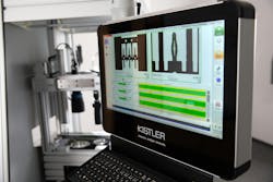
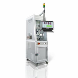
An inline inspection example of series-produced components using the Kistler KVC 621 SE optical quality inspection system illustrates what such a concept might look like.
This compact testing system for punched metal components can perform an optical inspection of up to 4,000 parts per minute to check for dimensional accuracy and surface defects such as scratches or dents. Up to three integrated camera stations take pictures of the test part enabling the KiVision image processing software to handle the evaluation and ensure that every part is inspected, even at high cycle rates.
The built-in camera stations and software for image processing are connected by the programmable logic controller (PLC), which initiates the individual steps such as recording of the test piece, data transfer and evaluation by the image processing software. It also checks the communication between the individual components. The camera, for example, sends the signal to the PLC when an image has been taken and transmits the image to the image processing software.
At this point, a problem can arise that computer users know only too well: parallel processes slow down data processing. If the camera delivers a new inspection image before the inspection of the last image has been completed, it can put additional strain on the software. In such cases, the PLC detects that the expected feedback is not being provided, stops the system and issues an error message to the operators, including the cause of the error. This ensures that the inspection system checks each part and defines its status as OK or NOK.
Another typical error source when testing punched parts in endless strips is the removal of NOK parts from the strip using a stamp. In such cases, it is not sufficient to identify a part as defective if it is not subsequently removed. Therefore, sensors monitor the up and down movement of the stamp to check its end position. An additional laser light barrier is also used to ensure that the NOK part has been separated — after all, a stamp stroke does not necessarily mean that a part has been completely separated.
Careful design of the inspection processes
When designing systems and the associated inspection processes, a range of potential errors could affect smooth operation. For example, individual requirements are almost always hidden in production processes as higher levels of automation are added. To ensure an error-free process, it is critical to analyze, implement and secure all crucial process and quality assurance steps accordingly.
For the Kistler Group, such considerations are part of every system design, as a failure mode and effects analysis after construction are integral to the design process. During this process, possible errors and their effects on the process are collected and evaluated.
Edgar Wuchrer works in vision technology business development EMEA at Kistler Group.
More quality-related content from Automation World:
About the Author

Leaders relevant to this article:

